How to Book a Roadworthy Inspection Online in Clayton
How to Book a Roadworthy Inspection Online in Clayton
Comprehending Typical Assessment Failings
Understanding usual assessment failings is crucial for anybody intending to quickly pass a roadworthy certificate evaluation. These examinations are made to make sure that automobiles meet particular security and exhaust requirements needed for road use. Understanding of normal risks can not just accelerate the procedure however additionally save money and time.
One of the most common assessment failings focuses on tire condition. Tires are vital for vehicle security, providing the needed grasp and stability. Assessors commonly look for adequate walk depth, indicators of unequal wear, and any noticeable damage like cuts or bulges. Making certain that tires are properly inflated and aligned can protect against a failure around.
Brakes are another critical part usually inspected during evaluations. Damage on brake pads, discs, or drums can lead to a stopping working quality. Routine upkeep and instant attention to any unusual sounds or reduced brake efficiency can reduce this danger. Its additionally a good idea to make certain the brake liquid is topped up and the handbrake is operating properly.
Illumination is a simple yet constant failing factor. Examiners will check the capability of all lights, consisting of headlights, tail lights, signs, and brake lights. Replacing any type of faulty light bulbs and making sure that lenses are tidy and devoid of fractures is crucial for passing this component of the assessment.
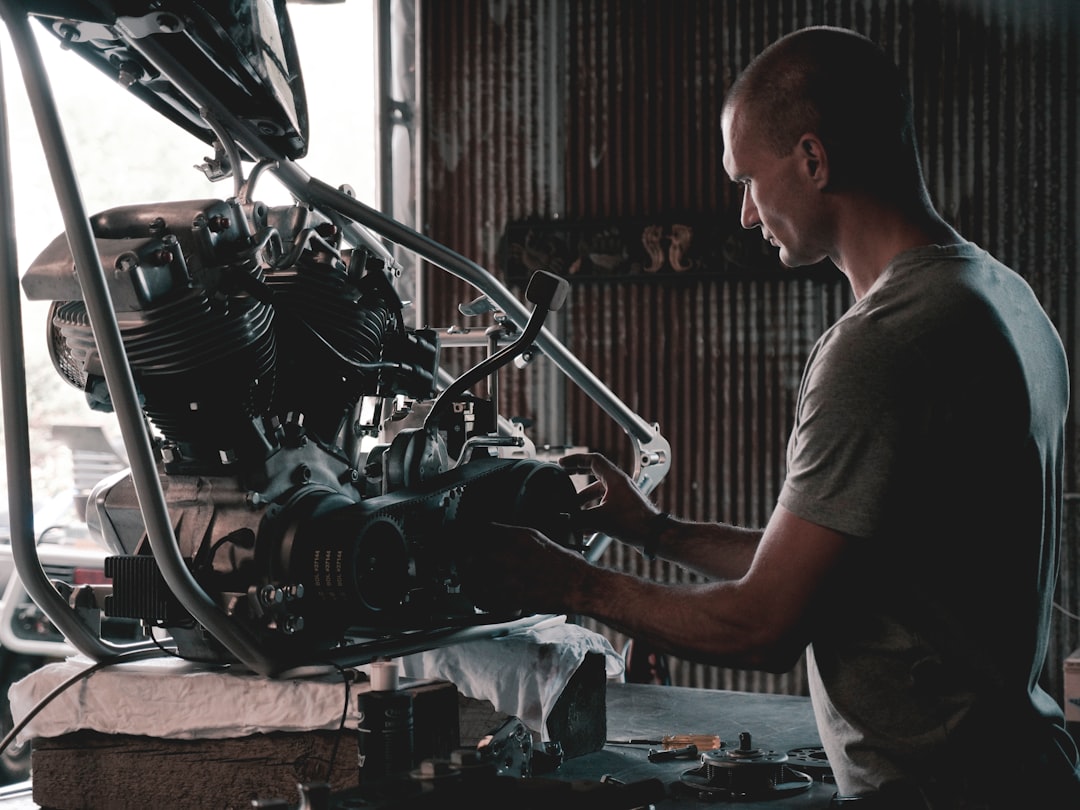
The cars shock absorber, while much less noticeable, is another location that can lead to assessment distress. Damaged shock absorbers or struts can influence vehicle handling and safety. If you discover too much bouncing after discussing bumps or a basic decrease in experience convenience, it could suggest suspension issues that need addressing before the inspection.
Emissions testing is an extra technical facet of the inspection that can frequently trip up vehicle proprietors. Modern automobiles are furnished with facility systems to minimize exhausts, and any malfunction within these systems can cause a failing. Regular engine servicing, including changing the oil and air filters, can help maintain the cars emission degrees within acceptable limitations.
Lastly, the general problem and performance of the vehicle are assessed. This consists of checking out the windscreen for fractures, ensuring that wipers remain in good functioning order, and looking for any structural corrosion or damages that can jeopardize safety.
In conclusion, understanding and resolving usual evaluation failings is crucial to passing a roadworthy certificate assessment effortlessly. Routine vehicle maintenance, focus to detail, and dealing with any well-known problems prior to the evaluation can dramatically boost the likelihood of an effective result. Remember, a roadworthy vehicle is not just about conformity; it's about making sure safety on your own and others when driving.
Preparing Your Vehicle for Evaluation
Preparing your vehicle for a roadworthy certificate examination could seem daunting, but with a little assistance and prep work, you can easily pass the evaluation and ensure your vehicle is safe and certified. The roadworthy certificate is an important file that validates your vehicle is suitabled for the road, and obtaining it is a necessary step in vehicle ownership, particularly if you plan to offer your car or register it in a brand-new state. Here's how to simplify the process and set on your own up for success.
First and foremost, acquaint on your own with the particular needs for a roadworthy certificate in your area. While these can vary from one region to one more, a lot of examinations concentrate on crucial safety aspects of your vehicle, such as brakes, tires, lights, and architectural honesty. Recognizing these needs will assist you prioritize what requires attention and stay clear of any last-minute surprises.
Begin by carrying out a complete self-inspection of your vehicle. Start with the outside: check that all lights and signs are operating effectively, as these are common factors of failing during examinations. Replace any burnt-out light bulbs, and ensure that your fronts lights are correctly lined up to avoid blinding other motorists. Examine your tires for sufficient walk deepness and proper inflation-- this not just improves safety but likewise improves gas effectiveness.
Next off, transfer to the inside. Examine seatbelts to ensure they remain in excellent functioning problem and show no signs of fraying or damages. Examine all dashboard indications and gauges to confirm they are functional. Pay special focus to the horn, as it must be distinct and trusted.
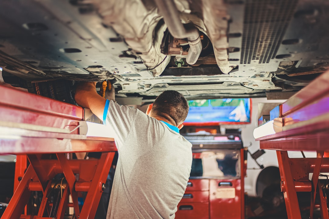
The under-the-hood assessment is similarly critical. Examine all fluid degrees, consisting of engine oil, brake liquid, and coolant, covering them up as essential. Check belts and tubes for any signs of wear or leakages. A well-maintained engine not just boosts your possibilities of passing the assessment but likewise extends the life of your vehicle.
Brakes are possibly the most essential part when it comes to safety and security. If you have actually seen any squealing, grinding, or reduced responsiveness, have them inspected by an expert. Used brake pads or harmed rotors should be replaced to ensure your vehicle quits safely and effectively.
Ultimately, make sure that your cars body is in excellent condition. While small scrapes might not be an issue, substantial rust or damages could lead to a failing, as they can compromise architectural integrity. Deal with any type of such issues before the assessment.
To conclude, preparing your vehicle for a roadworthy certificate inspection is all about interest to detail and dealing with potential problems ahead of time. By adhering to these actions, you not just enhance your chances of passing the evaluation yet also contribute to the overall safety and security and reliability of your vehicle. Remember, a well-maintained car is not just about conformity; it's about making certain the safety of every person when traveling.
What to Anticipate Throughout the Evaluation Process
Acquiring a roadworthy certificate is an important action in guaranteeing that your vehicle is safe for usage on the road. The assessment process might appear complicated, specifically if you're unfamiliar with what it requires. Nonetheless, understanding what to anticipate can make the experience extra manageable and raise your opportunities of passing on the first attempt.
Most importantly, its essential to understand that the examination procedure is developed to assess the safety and performance of your vehicle. Throughout the inspection, a licensed technician or assessment officer will meticulously check out various elements of your car. These generally consist of vital areas such as brakes, tires, steering, suspension, lights, and the general architectural honesty of the vehicle. The objective is to make sure that each part remains in great working problem and meets the requirements set by neighborhood policies.
Before heading to the assessment, its important to perform an initial check yourself. Begin with the essentials: ensure that all lights are working, consisting of fronts lights, brake lights, and transform signals. Analyze your tires for appropriate walk depth and proper inflation, as this is an usual point of failing. Additionally, examine the brakes by listening for unusual sounds and making sure a company pedal really feel. It's additionally a great concept to evaluate the windscreen for any kind of fractures or chips that can hinder presence, in addition to making certain that windshield wipers are in good condition.
During the evaluation, the technician will likely carry out a collection of examinations. For example, they might use customized tools to measure brake effectiveness or to guarantee that the wheel alignment is within appropriate parameters. They will certainly additionally examine under the hood to assess the problem of the engine, transmission, and exhaust system. Its essential to be mindful that any fluid leakages or too much discharges can lead to an unsuccessful inspection.
The structural honesty of the vehicle is one more essential facet. The examiner will try to find indications of corrosion or damages to the frame that might compromise safety and security. They will also check the capability of seat belts and air bags, making certain that they satisfy security criteria.
To enhance your opportunities of passing the examination, routine maintenance is crucial. Remaining on top of routine solutions, such as oil changes and brake pad replacements, can prevent tiny problems from coming to be larger problems. If you're uncertain concerning the problem of your vehicle, think about having it serviced by a trusted mechanic prior to the official evaluation. They can provide a specialist evaluation and deal with any kind of possible problems beforehand.
In summary, understanding what to expect throughout the roadworthy evaluation procedure can ease anxiety and help you prepare properly. Need a roadworthy inspections in Clayton with a trusted local workshop. By taking aggressive actions to guarantee that your vehicle remains in excellent problem, you can improve your safety and security when traveling and make the examination procedure a straightforward experience. Bear in mind, the best objective is not just to pass the examination yet to make sure that your vehicle is secure for you and others on the road.
Post-Inspection: Next Actions and Tips
After successfully browsing the roadworthy certificate assessment, lots of vehicle owners take a breath a sigh of relief. Nevertheless, passing the assessment is just the beginning of keeping a risk-free and trusted vehicle. Post-inspection, there are a number of positive actions and tips that can aid guarantee your vehicle stays in top problem and prepared for the road in all times.
To start with, it is crucial to comprehend that the roadworthy certificate is a representation of your vehicles problem at the time of examination. To keep this status, routine maintenance checks must be a priority. On a regular basis set up servicing with a trusted technician can help address potential concerns prior to they end up being significant problems. This is particularly important for parts such as brakes, tires, and lights, which are important for vehicle safety and security.
One more important step is to address any type of advisory notes or minor issues highlighted throughout the inspection. Also if these problems did not avoid you from passing, they can deteriorate with time and lead to a lot more serious troubles. By resolving these worries quickly, you guarantee your vehicle remains safe and effective.
Keeping a thorough record of all maintenance and repairs is another ideal practice post-inspection. This not just helps track the vehicle's problem yet likewise adds value when it comes time to sell the vehicle. Potential buyers appreciate a well-documented solution background as it gives understanding into just how well the vehicle has actually been preserved.
In addition, remaining educated concerning adjustments in roadworthy laws and standards is beneficial. These requirements can alter in time, and remaining upgraded makes certain that your vehicle will continue to fulfill necessary needs in the future. Engaging with neighborhood auto communities or signing up for industry newsletters can be an exceptional means to remain informed.
It is additionally wise to exercise protective driving and comply with road guidelines. This not only promotes safety and security however likewise decreases damage on your vehicle. Preventing rough braking, rapid acceleration, and overloading can prolong the life of your vehicle's components.
To conclude, passing your roadworthy certificate examination is a considerable success, however it is not the endpoint. By devoting to routine maintenance, attending to small concerns quickly, keeping extensive service records, staying informed regarding guidelines, and driving responsibly, you guarantee that your vehicle stays secure and roadworthy for years ahead. These steps not only safeguard your financial investment yet likewise add to a much safer driving environment for everybody when driving.
Part of car suspension system consists of shock absorber, axle, frame and springPart of car front suspension and steering mechanism: tie rod, steering arm, king pin axis (using ball joints).Van Diemen RF01 racing car suspension
Suspension is the system of tires, tire air, springs, shock absorbers and linkages that connects a vehicle to its wheels and allows relative motion between the two.[1] Suspension systems must support both road holding/handling and ride quality,[2] which are at odds with each other. The tuning of suspensions involves finding the right compromise. The suspension is crucial for maintaining consistent contact between the road wheel and the road surface, as all forces exerted on the vehicle by the road or ground are transmitted through the tires' contact patches. The suspension also protects the vehicle itself and any cargo or luggage from damage and wear. The design of front and rear suspension of a car may be different.
American stagecoach showing thoroughbrace suspension—note the black straps under the curved body of the coach
An early form of suspension on ox-drawn carts had the platform swing on iron chains attached to the wheeled frame of the carriage. This system remained the basis for most suspension systems until the turn of the 19th century, although the iron chains were replaced with the use of leather straps called thoroughbraces by the 17th century. No modern automobiles have used the thoroughbrace suspension system.
By approximately 1750, leaf springs began appearing on certain types of carriage, such as the Landau.[3]
By the middle of the 19th century, elliptical springs might additionally start to be used on carriages.
The front suspension components of a Ford Model T.
Automobiles were initially developed as self-propelled versions of horse-drawn vehicles. However, horse-drawn vehicles had been designed for relatively slow speeds, and their suspension was not well suited to the higher speeds permitted by the internal combustion engine.
The first workable spring-suspension required advanced metallurgical knowledge and skill, and only became possible with the advent of industrialisation. Obadiah Elliott registered the first patent for a spring-suspension vehicle; each wheel had two durable steel leaf springs on each side and the body of the carriage was fixed directly to the springs which were attached to the axles. Within a decade, most British horse carriages were equipped with springs; wooden springs in the case of light one-horse vehicles to avoid taxation, and steel springs in larger vehicles. These were often made of low-carbon steel and usually took the form of multiple layer leaf springs.[4]
Leaf springs have been around since the early Egyptians. Ancient military engineers used leaf springs in the form of bows to power their siege engines, with little success at first. The use of leaf springs in catapults was later refined and made to work years later. Springs were not only made of metal; a sturdy tree branch could be used as a spring, such as with a bow. Horse-drawn carriages and Ford Model T used this system, and it is still used today in larger vehicles, mainly mounted in the rear suspension.[5]
Leaf springs were the first modern suspension system, and, along with advances in the construction of roads, heralded the single greatest improvement in road transport until the advent of the automobile.[6] The British steel springs were not well-suited for use on America's rough roads of the time, so the Abbot-Downing Company of Concord, New Hampshire re-introduced leather strap suspension, which gave a swinging motion instead of the jolting up-and-down of spring suspension.
Henri Fournier on his uniquely damped and racewinning 'Mors Machine', photo taken 1902
In 1901, Mors of Paris first fitted an automobile with shock absorbers. With the advantage of a damped suspension system on his 'Mors Machine', Henri Fournier won the prestigious Paris-to-Berlin race on 20 June 1901. Fournier's superior time was 11 hours 46 minutes and 10 seconds, while the best competitor was Léonce Girardot in a Panhard with a time of 12 hours, 15 minutes, and 40 seconds.[7]
In 1922, independent front suspension was pioneered on Lancia Lambda, and became more common in mass market cars from 1932.[8] Today, most cars have independent suspension on all four wheels.
The part on which pre-1950 springs were supported is called a dumb iron.
In 2002, a new passive suspension component, the inerter, was invented by Malcolm C. Smith. This has the ability to increase the effective inertia of wheel suspension using a geared flywheel, but without adding significant mass. It was initially employed in Formula One in secrecy, but has since spread to wider motorsport.
Difference between rear suspension and front suspension
Henry Ford's Model T used a torque tube to restrain this force, for his differential was attached to the chassis by a lateral leaf spring and two narrow rods. The torque tube surrounded the true driveshaft and exerted the force to its ball joint at the extreme rear of the transmission, which was attached to the engine. A similar method like this was used in the late 1930s by Buick and by Hudson's bathtub car in 1948, which used helical springs that could not take fore-and-aft thrust.
The Hotchkiss drive, invented by Albert Hotchkiss, was the most popular rear suspension system used in American cars from the 1930s to the 1970s. The system uses longitudinal leaf springs attached both forward and behind the differential of the live axle. These springs transmit torque to the frame. Although scorned by many European car makers of the time, it was accepted by American car makers, because it was inexpensive to manufacture. Also, the dynamic defects of this design were suppressed by the enormous weight of U.S. passenger vehicles before the implementation of the Corporate Average Fuel Economy (CAFE) standard.
Another Frenchman invented the De Dion tube, which is sometimes called "semi-independent". Like true independent rear suspension, this employs two universal joints, or their equivalent from the centre of the differential to each wheel. But the wheels cannot entirely rise and fall independently of each other; they are tied by a yoke that goes around the differential, below and behind it. This method has had little use in the United States. Its use around 1900 was probably due to the poor quality of tires, which wore out quickly. By removing a good deal of unsprung weight, as independent rear suspensions do, it made them last longer.[citation needed]
Rear-wheel drive vehicles today frequently use a fairly complex fully-independent, multi-link suspension to locate the rear wheels securely, while providing decent ride quality.[citation needed]
The spring rate (or suspension rate) is a component in setting the vehicle's ride height or its location in the suspension stroke. When a spring is compressed or stretched, the force it exerts, is proportional to its change in length. The spring rate or spring constant of a spring is the change in the force it exerts, divided by the change in deflection of the spring. Vehicles that carry heavy loads, will often have heavier springs to compensate for the additional weight that would otherwise collapse a vehicle to the bottom of its travel (stroke). Heavier springs are also used in performance applications, where the loading conditions experienced are more significant.
Springs that are too hard or too soft cause the suspension to become ineffective – mostly because they fail to properly isolate the vehicle from the road. Vehicles that commonly experience suspension loads heavier than normal, have heavy or hard springs, with a spring rate close to the upper limit for that vehicle's weight. This allows the vehicle to perform properly under a heavy load, when control is limited by the inertia of the load. Riding in an empty truck meant for carrying loads can be uncomfortable for passengers, because of its high spring rate relative to the weight of the vehicle. A race car could also be described as having heavy springs, and would also be uncomfortably bumpy. However, even though we say they both have heavy springs, the actual spring rates for a 2,000 lb (1,000 kg) racecar and a 10,000 lb (5,000 kg) truck are very different. A luxury car, taxi, or passenger bus would be described as having soft springs, for the comfort of their passengers or driver. Vehicles with worn-out or damaged springs ride lower to the ground, which reduces the overall amount of compression available to the suspension, and increases the amount of body lean. Performance vehicles can sometimes have spring rate requirements other than vehicle weight and load.
Wheel rate is the effective spring rate when measured at the wheel, as opposed to simply measuring the spring rate alone.
Wheel rate is usually equal to or considerably less than the spring rate. Commonly, springs are mounted on control arms, swing arms or some other pivoting suspension member. Consider the example above, where the spring rate was calculated to be 500 lbs/inch (87.5 N/mm), if one were to move the wheel 1 in (2.5 cm) (without moving the car), the spring more than likely compresses a smaller amount. If the spring moved 0.75 in (19 mm), the lever arm ratio would be 0.75:1. The wheel rate is calculated by taking the square of the ratio (0.5625) times the spring rate, thus obtaining 281.25 lbs/inch (49.25 N/mm). The ratio is squared because it has two effects on the wheel rate: it applies to both the force and the distance traveled.
Wheel rate on independent suspension is fairly straightforward. However, special consideration must be taken with some non-independent suspension designs. Take the case of the straight axle. When viewed from the front or rear, the wheel rate can be measured by the means above. Yet, because the wheels are not independent, when viewed from the side under acceleration or braking, the pivot point is at infinity (because both wheels have moved) and the spring is directly inline with the wheel contact patch. The result is often, that the effective wheel rate under cornering is different from what it is under acceleration and braking. This variation in wheel rate may be minimised by locating the spring as close to the wheel as possible.
Wheel rates are usually summed and compared with the sprung mass of a vehicle to create a "ride rate" and the corresponding suspension natural frequency in ride (also referred to as "heave"). This can be useful in creating a metric for suspension stiffness and travel requirements for a vehicle.
Roll rate is analogous to a vehicle's ride rate, but for actions that include lateral accelerations, causing a vehicle's sprung mass to roll. It is expressed as torque per degree of roll of the vehicle sprung mass. It is influenced by factors including but not limited to vehicle sprung mass, track width, CG height, spring and damper rates, roll centre heights of front and rear, anti-roll bar stiffness and tire pressure/construction. The roll rate of a vehicle can, and usually, does differ front-to-rear, which allows for the tuning ability of a vehicle for transient and steady-state handling. The roll rate of a vehicle does not change the total amount of weight transfer on the vehicle, but shifts the speed and percentage of weight transferred on a particular axle to another axle through the vehicle chassis. Generally, the higher the roll rate on an axle of a vehicle, the faster and higher percentage the weight transfer on that axle.[citation needed]
By 2021, some vehicles were offering dynamic roll control with ride-height adjustable air suspension and adaptive dampers.[9]
Roll couple percentage is a simplified method of describing lateral load transfer distribution front to rear, and subsequently handling balance. It is the effective wheel rate, in roll, of each axle of the vehicle as a ratio of the vehicle's total roll rate. It is commonly adjusted through the use of anti-roll bars, but can also be changed through the use of different springs.
Weight transfer during cornering, acceleration, or braking is usually calculated per individual wheel, and compared with the static weights for the same wheels.
The total amount of weight transfer is only affected by four factors: the distance between wheel centers (wheelbase in the case of braking, or track width in the case of cornering), the height of the center of gravity, the mass of the vehicle, and the amount of acceleration experienced.
The speed at which weight transfer occurs, as well as through which components it transfers, is complex, and is determined by many factors; including, but not limited to: roll center height, spring and damper rates, anti-roll bar stiffness, and the kinematic design of suspension links.
In most conventional applications, when weight is transferred through intentionally compliant elements, such as springs, dampers, and anti-roll bars, the weight transfer is said to be "elastic", while the weight which is transferred through more rigid suspension links, such as A-arms and toe links, is said to be "geometric".
Unsprung weighttransfer is calculated based on weight of the vehicle's components that are not supported by the springs. This includes tires, wheels, brakes, spindles, half the control arm's weight, and other components. These components are then (for calculation purposes) assumed to be connected to a vehicle with zero sprung weight. They are then put through the same dynamic loads.
The weight transfer for cornering in the front would be equal to the total unsprung front weight times the G-force times the front unsprung center of gravity height divided by the front track width. The same is true for the rear.
Sprung weight transfer is the weight transferred by only the weight of the vehicle resting on its springs, and not by total vehicle weight. Calculating this requires knowing the vehicle's sprung weight (total weight less the unsprung weight), the front and rear roll center heights, and the sprung center of gravity height (used to calculate the roll moment arm length). Calculating the front and rear sprung weight transfer will also require knowing the roll couple percentage.
The roll axis is the line through the front and rear roll centers that the vehicle rolls around during cornering. The distance from this axis to the sprung center of gravity height is the roll moment arm length. The total sprung weight transfer is equal to the G-force times the sprung weight times the roll moment arm length divided by the effective track width. The front sprung weight transfer is calculated by multiplying the roll couple percentage times the total sprung weight transfer. The rear is the total minus the front transfer.
Jacking forces are the sum of the vertical force components experienced by suspension links. The resultant force acts to lift the sprung mass, if the roll center is above ground, or compress it, if underground. Generally, the higher the roll center, the more jacking force is experienced.
Travel is the measure of distance from the bottom of the suspension stroke (such as when the vehicle is on a jack, and the wheel hangs freely) to the top of the suspension stroke (such as when the vehicle's wheel can no longer travel in an upward direction toward the vehicle). Bottoming or lifting a wheel can cause serious control problems, or directly cause damage. "Bottoming" can be caused by the suspension, tires, fenders, etc. running out of space to move, or the body or other components of the car hitting the road. Control problems caused by lifting a wheel are less severe, if the wheel lifts when the spring reaches its unloaded shape than they are, if travel is limited by contact of suspension members (See Triumph TR3B.)
Many off-road vehicles, such as desert racers, use straps called "limiting straps" to limit the suspensions' downward travel to a point within safe limits for the linkages and shock absorbers. This is necessary, since these trucks are intended to travel over very rough terrain at high speeds, and even become airborne at times. Without something to limit the travel, the suspension bushings would take all the force, when suspension reaches "full droop", and it can even cause the coil springs to come out of their "buckets", if they are held in by compression forces only. A limiting strap is a simple strap, often from nylon of a predetermined length, that stops downward movement at a pre-set point before theoretical maximum travel is reached. The opposite of this is the "bump-stop", which protects the suspension and the vehicle (as well as the occupants) from the violent "bottoming" of the suspension, caused when an obstruction (or a hard landing) causes suspension to run out of upward travel without fully absorbing the energy of the stroke. Without bump-stops, a vehicle that "bottoms out", will experience a very hard shock when the suspension contacts the bottom of the frame or body, which is transferred to the occupants and every connector and weld on the vehicle. Factory vehicles often come with plain rubber "nubs" to absorb the worst of the forces, and insulate the shock. A desert race vehicle, which must routinely absorb far higher impact forces, might be provided with pneumatic or hydro-pneumatic bump-stops. These are essentially miniature shock absorbers (dampers) that are fixed to the vehicle in a location, such, that the suspension will contact the end of the piston when it nears the upward travel limit. These absorb the impact far more effectively than a solid rubber bump-stop will, essential, because a rubber bump-stop is considered a "last-ditch" emergency insulator for the occasional accidental bottoming of the suspension; it is entirely insufficient to absorb repeated and heavy bottoming, such as a high-speed off-road vehicle encounters.
Damping is the control of motion or oscillation, as seen with the use of hydraulic gates and valves in a vehicle's shock absorber. This may also vary, intentionally or unintentionally. Like spring rate, the optimal damping for comfort may be less, than for control.
Damping controls the travel speed and resistance of the vehicle's suspension. An undamped car will oscillate up and down. With proper damping levels, the car will settle back to a normal state in a minimal amount of time. Most damping in modern vehicles can be controlled by increasing or decreasing the resistance to fluid flow in the shock absorber.
See dependent and independent below. Camber changes due to wheel travel, body roll and suspension system deflection or compliance. In general, a tire wears and brakes best at -1 to -2° of camber from vertical. Depending on the tire and the road surface, it may hold the road best at a slightly different angle. Small changes in camber, front and rear, can be used to tune handling. Some racecars are tuned with -2 to -7° camber, depending on the type of handling desired, and tire construction. Often, too much camber will result in the decrease of braking performance due to a reduced contact patch size through excessive camber variation in suspension geometry. The amount of camber change in bump is determined by the instantaneous front view swing arm (FVSA) length of suspension geometry, or in other words, the tendency of the tire to camber inward when compressed in bump.
Roll center height is a product of suspension instant center heights and is a useful metric in analyzing weight transfer effects, body roll and front to rear roll stiffness distribution. Conventionally, roll stiffness distribution is tuned adjusting antiroll bars rather than roll center height (as both tend to have a similar effect on the sprung mass), but the height of the roll center is significant when considering the amount of jacking forces experienced.
Due to the fact that the wheel and tire's motion is constrained by the vehicle's suspension links, the motion of the wheel package in the front view will scribe an imaginary arc in space with an "instantaneous center" of rotation at any given point along its path. The instant center for any wheel package can be found by following imaginary lines drawn through suspension links to their intersection point.
A component of the tire's force vector points from the contact patch of the tire through instant center. The larger this component is, the less suspension motion will occur. Theoretically, if the resultant of the vertical load on the tire and the lateral force generated by it points directly into the instant center, the suspension links will not move. In this case, all weight transfer at that end of the vehicle will be geometric in nature. This is key information used in finding the force-based roll center as well.
In this respect, the instant centers are more important to the handling of the vehicle, than the kinematic roll center alone, in that the ratio of geometric-to-elastic weight transfer is determined by the forces at the tires and their directions in relation to the position of their respective instant centers.
Anti-dive and anti-squat are percentages that indicate the degree to which the front dives under braking, and the rear squats under acceleration. They can be thought of as the counterparts for braking and acceleration, as jacking forces are to cornering. The main reason for the difference is due to the different design goals between front and rear suspension, whereas suspension is usually symmetrical between the left and the right of the vehicle.
The method of determining anti-dive or anti-squat depends on whether suspension linkages react to the torque of braking and accelerating. For example, with inboard brakes and half-shaft-driven rear wheels, the suspension linkages do not react, but with outboard brakes and a swing-axle driveline, they do.
To determine the percentage of front suspension braking anti-dive for outboard brakes, it is first necessary to determine the tangent of the angle between a line drawn, in side view, through the front tire patch and the front suspension instant center, and the horizontal. In addition, the percentage of braking effort at the front wheels must be known. Then, multiply the tangent by the front wheel braking effort percentage and divide by the ratio of the center of gravity height to the wheelbase. A value of 50% would mean, that half of the weight transfer to the front wheels; during braking, it is being transmitted through front suspension linkage, and half is being transmitted through front suspension springs.
For inboard brakes, the same procedure is followed, but using the wheel center instead of contact patch center.
Forward acceleration anti-squat is calculated in a similar manner and with the same relationship between percentage and weight transfer. Anti-squat values of 100% and more are commonly used in drag racing, but values of 50% or less are more common in cars that have to undergo severe braking. Higher values of anti-squat commonly cause wheel hop during braking. It is important to note, that the value of 100% means, that all of the weight transfer is being carried through suspension linkage. However, this does not mean that the suspension is incapable of carrying additional loads (aerodynamic, cornering, etc.) during an episode of braking, or forward acceleration. In other words, no "binding" of the suspension is to be implied.[10]
Flexibility and vibration modes of suspension elements
In some modern cars, flexibility is mainly in rubber bushings, which are subject to decay over time. For high-stress suspensions, such as off-road vehicles, polyurethane bushings are available, which offer more longevity under greater stresses. However, due to weight and cost considerations, structures are not made more rigid than necessary. Some vehicles exhibit detrimental vibrations involving the flexing of structural parts, such as when accelerating while turning sharply. Flexibility of structures, such as frames and suspension links, can also contribute to springing, especially to damping out high-frequency vibrations. The flexibility of wire wheels contributed to their popularity in times when cars had less advanced suspensions.
Automobiles can be heavily laden with luggage, passengers, and trailers. This loading will cause a vehicle's tail to sink downwards. Maintaining a steady chassis level is essential to achieving the proper handling that the vehicle was designed for. Also, if the car's nose is too elevated when driving at night, oncoming drivers can be blinded by the headlight beam. Self-levelling suspension counteracts this by inflating cylinders in the suspension to lift the chassis higher.[11]
For most purposes, the weight of suspension components is unimportant. But at high frequencies caused by road surface roughness, the parts isolated by rubber bushings act as a multi-stage filter to suppress noise and vibration better than can be done with only tires and springs. (The springs work mainly in the vertical direction.)
These are usually small, except that the suspension is related to whether the brakes and differential(s) are sprung.
This is the main functional advantage of aluminum wheels over steel wheels. Aluminum suspension parts have been used in production cars, and carbon fiber suspension parts are common in racing cars.
Designs differ as to how much space they take up, and where it is located. It is generally accepted, that MacPherson struts are the most compact arrangement for front-engined vehicles, where space between the wheels is required to place the engine.
Inboard brakes (which reduce unsprung weight) are probably avoided more due to space considerations than to cost.
Certain modern vehicles have height adjustable suspension in order to improve aerodynamics and fuel efficiency. Modern formula cars that have exposed wheels and suspension typically use streamlined tubing rather than simple round tubing for their suspension arms to reduce aerodynamic drag. Also typical is the use of rocker-arm, push rod, or pull rod-type suspensions, that, among other things, place the spring/damper unit inboard and out of the air stream to further reduce air resistance.
Production methods improve, but cost is always a factor. The continued use of the solid rear axle, with unsprung differential, especially on heavy vehicles, seems to be the most obvious example.
Most conventional suspensions use passive springs to absorb impacts and dampers (or shock absorbers) to control spring motions.
Some notable exceptions are hydropneumatic systems, which can be treated as an integrated unit of gas spring and damping components, used by the French manufacturer Citroën; and the hydrolastic, hydragas and rubber cone systems used by the British Motor Corporation, most notably on the Mini. A number of different types of each have been used:
Automakers are aware of the inherent limitations of steel springs — that these springs tend to produce undesirable oscillations, and carmakers have developed other types of suspension materials and mechanisms in attempts to improve performance:
Shock absorbers damp out the (otherwise simple harmonic) motions of a vehicle up and down on its springs. They must also damp out much of the wheel bounce when the unsprung weight of a wheel, hub, axle, and sometimes brakes and the differential bounces up and down on the springiness of a tire.
If suspension is externally controlled, then it is a semi-active or active suspension — the suspension is reacting to signals from an electronic controller.
For example, a hydropneumatic Citroën will "know" how far off the ground the car is supposed to be, and constantly resets to achieve that level, regardless of load. However, this type of suspension will not instantly compensate for body roll due to cornering. Citroën's system adds about 1% to the cost of the car versus passive steel springs.
Toyota introduced switchable shock absorbers in the 1983 Soarer.[17] Delphi currently sells shock absorbers filled with a magneto-rheological fluid, whose viscosity can be changed electromagnetically — thereby giving variable control without switching valves, which is faster and thus more effective.
Fully active suspension systems use electronic monitoring of vehicle conditions, coupled with the means to change the behavior of vehicle suspension in real time to directly control the motion of the car.
Lotus Cars developed several prototypes from 1982 onwards, and introduced them to Formula One, where they have been fairly effective, but have now been banned.
Nissan introduced low-bandwidth active suspension circa 1990 as an option that added an extra 20% to the price of luxury models. Citroën has also developed several active suspension models (see hydractive). A fully active system from Bose Corporation, announced in 2009, uses linear electric motors[18][19][20][21][22] in place of hydraulic or pneumatic actuators that have generally been used up until recently. Mercedes introduced an active suspension system called Active Body Control in its top-of-the-line Mercedes-Benz CL-Class in 1999.
Several electromagnetic suspensions have also been developed for vehicles. Examples include the electromagnetic suspension of Bose, and the electromagnetic suspension developed by prof. Laurentiu Encica. In addition, the new Michelin wheel with embedded suspension functioning on an electric motor is also similar.[23]
With the help of a control system, various semi-active/active suspensions realize an improved design compromise among different vibration modes of the vehicle; namely: bounce, roll, pitch and warp modes. However, the applications of these advanced suspensions are constrained by cost, packaging, weight, reliability, and/or other challenges.
Interconnected suspension, unlike semi-active/active suspensions, could easily decouple different vehicle vibration modes in a passive manner. Interconnections can be realized by various means, such as mechanical, hydraulic, and pneumatic. Anti-roll bars are one of the typical examples of mechanical interconnections, while it has been stated, that fluidic interconnections offer greater potential and flexibility in improving both the stiffness and damping properties.
Considering the considerable commercial potentials of hydro-pneumatic technology (Corolla, 1996), interconnected hydropneumatic suspensions have also been explored in some recent studies, and their potential benefits in enhancing vehicle ride and handling have been demonstrated. The control system can also be used for further improving performance of interconnected suspensions. Apart from academic research, an Australian company Kinetic[24] had some success with various passive or semi-active systems (WRC: three Championships; the Dakar Rally: two Championships; Lexus GX470 2004 as the 4×4 of the year with KDSS; the 2005 PACE award). These systems by Kinetic generally decouple at least two vehicle modes (roll, warp (articulation), pitch, and/or heave (bounce)) to simultaneously control each mode's stiffness and damping by using interconnected shock absorbers, and other methods. In 1999, Kinetic was bought out by Tenneco. Later developments by the Catalan company Creuat have devised a simpler system design based on single-acting cylinders. After some projects on competition, Creuat is active in providing retrofit systems for some vehicle models.
Historically, the first mass-production car with front-to-rear mechanical interconnected suspension was the 1948 Citroën 2CV. Suspension in the 2CV was extremely soft — the longitudinal link was making pitch softer, instead of making roll stiffer. It relied on extreme anti-dive and anti-squat geometries to compensate for that. This resulted in a softer axle-crossing stiffness that anti-roll bars would have otherwise compromised. The leading arm / trailing arm swinging arm, fore-aft linked suspension system, together with in-board front brakes, had a much smaller unsprung weight than existing coil spring or leaf designs. The interconnection transmitted some of the force deflecting a front wheel up over a bump, to push the rear wheel down on the same side. When the rear wheel met that bump a moment later, it did the same in reverse, keeping the car level front to rear. The 2CV had a design brief to be able to be driven at speed over a ploughed field, such as by a farmer transporting chicken eggs. It originally featured friction dampers and tuned mass dampers. Later models had tuned mass dampers at the front with telescopic dampers/shock absorbers front and rear.
British Motor Corporation was also an early adopter of interconnected suspension. A system dubbed Hydrolastic was introduced in 1962 on Morris 1100, and went on to be used on a variety of BMC models. Hydrolastic was developed by suspension engineer Alex Moulton, and used rubber cones as the springing medium (these were first used on the 1959 Mini) with suspension units on each side connected to each other by a fluid-filled pipe. The fluid transmitted the force of road bumps from one wheel to the other (on the same principle as Citroën 2CV's mechanical system described above), and because each suspension unit contained valves to restrict the flow of fluid, also served as a shock absorber.[25] Moulton went on to develop a replacement for Hydrolastic for BMC's successor British Leyland. This system, manufactured under licence by Dunlop in Coventry, called Hydragas, worked with the same principle, but instead of rubber spring units, it used metal spheres divided internally by a rubber diaphragm. The top half contained pressurised gas, and the lower half the same fluid as used on the Hydrolastic system. The fluid transmitted suspension forces between the units on each side, whilst the gas acted as the springing medium through the diaphragm. This is the same principle as the Citroën hydropneumatic system, and provides similar ride quality, but is self-contained, and does not require an engine-driven pump to provide hydraulic pressure. The downside is, that Hydragas is, unlike the Citroën system, not height-adjustable, or self-levelling. Hydragas was introduced in 1973 on Austin Allegro, and was used on several models; the last car to use it being MG F in 2002. The system was changed in favour of coil springs over dampers due to cost reasons towards the end of the vehicle's life. When it was decommissioned in 2006, the Hydragas manufacturing line was over 40 years old.
Some of the last post-war Packard models also featured interconnected suspension.
This diagram is not exhaustive; notably, it excludes elements, such as trailing arm links, and those that are flexible.
Suspension systems can be broadly classified into two subgroups: dependent and independent. These terms refer to the ability of opposite wheels to move independently of each other.[26] A dependent suspension normally has a beam (a simple 'cart' axle) or a (driven) live axle that holds wheels parallel to each other and perpendicular to the axle. When the camber of one wheel changes, the camber of the opposite wheel changes in the same way (by convention, on one side, this is a positive change in the camber, and on the other side, this a negative change). De Dion suspensions are also in this category, as they rigidly connect the wheels together.
Independent suspension allows wheels to rise and fall on their own without affecting the opposite wheel. Suspensions with other devices, such as sway bars that link the wheels in some way, are still classed as independent.
Semi-dependent suspension is a third type. In this case, the motion of one wheel does affect the position of the other, but they are not rigidly attached to each other. Twist-beam rear suspension is such a system.
Dependent systems may be differentiated by the system of linkages used to locate them, both longitudinally and transversely. Often, both functions are combined in a set of linkages.
Leaf springs used for location (transverse or longitudinal)
Fully elliptical springs usually need supplementary location links, and are no longer in common use
Longitudinal semi-elliptical springs used to be common, and are still used in heavy-duty trucks and aircraft. They have the advantage, that the spring rate can easily be made progressive (non-linear).
A single transverse leaf spring for both front wheels and/or both back wheels, supporting solid axles, was used by Ford Motor Company, before and soon after World War II, even on expensive models. It had the advantages of simplicity and low unsprung weight (compared to other solid-axle designs).
In a front-engine rear-drive vehicle, dependent rear suspension is either "live-axle" or deDion axle, depending on whether or not differential is carried on the axle. Live-axle is simpler, but unsprung weight contributes to wheel bounce.
Because it assures constant camber, dependent (and semi-independent) suspension is most common on vehicles that need to carry large loads as a proportion of the vehicle's weight, that have relatively soft springs and that do not (for cost and simplicity reasons) use active suspensions. The use of dependent front suspension has become limited to heavier commercial vehicles.
Transverse leaf springs when used as a suspension link, or four-quarter elliptics on one end of a car are similar to wishbones in geometry, but are more compliant. Examples are the front of the original Fiat 500, then Panhard Dyna Z, and the early examples of Peugeot 403, and the backs of AC Ace and AC Aceca.
Because the wheels are not constrained to remain perpendicular to a flat road surface in turning, braking, and varying load conditions, control of the wheel camber is an important issue. Swinging-arm was common in small cars that were sprung softly, and could carry large loads, because the camber is independent of load. Some active and semi-active suspensions maintain ride height, and therefore the camber, independent of load. In sports cars, optimal camber change when turning, is more important.
Wishbone and multi-link allow the engineer more control over the geometry, to arrive at the best compromise, than swing axle, MacPherson strut, or swinging arm do; however, the cost and space requirements may be greater.
Semi-trailing arm is in between, being a variable compromise between the geometries of swinging arm and swing axle.
In semi-independent suspensions, the wheels of an axle are able to move relative to one another, as in an independent suspension, but the position of one wheel has an effect on the position and attitude of the other wheel. This effect is achieved through the twisting or deflecting of suspension parts under load.
The most common type of semi-independent suspension is the twist beam.
The Tilting Suspension System[27] (also known as the Leaning Suspension System) is not a different type or geometry of construction; moreover, it is a technology addition to the conventional suspension system.
This kind of suspension system mainly consists of independent suspension (e.g., MacPherson strut, A-arm (double wishbone)). With the addition of these suspension systems, there is a further tilting or leaning mechanism that connects the suspension system with the vehicle body (chassis).
The tilting suspension system improves stability, traction, the turning radius of a vehicle, and the comfort of riders as well. While turning right or left, passengers or objects on a vehicle feel the G-force or inertial force outward the radius of the curvature, which is why two-wheeler riders (motorbikes) lean towards the center of curvature while turning, which improves stability and decreases the chances of toppling. But vehicles with more than two wheels, and equipped with a conventional suspension system, could not do the same until now, so the passengers feel the outward inertial force, which reduces the stability of riders and their comfort as well. This kind of tilting suspension system is the solution to the problem. If the road does not have super-elevation or banking, it will not affect the comfort with this suspension system, the vehicle tilt and decrease in the height of the center of gravity with an increase in stability. This suspension is also used in fun vehicles.
Some trains also use tilting suspension (Tilting Train) which increases the speed at cornering.
The rocker-bogie system is a suspension arrangement, in which there are some trailing arms fitted with some idler wheels. Due to articulation between the driving section and the followers, this suspension is very flexible. This kind of suspension is appropriate for extremely rough terrain.
This kind of suspension was used in the Curiosity rover.
Some vehicles, such as trains, run on long rail tracks fixed to the ground; and some, such as tractors, snow vehicles, and tanks run on continuous tracks that are part of the vehicle. Although either sort helps to smooth the path and reduce ground pressure, many of the same considerations apply.
This Grant I tank's suspension has road wheels mounted on wheel trucks, or bogies.
Military armoured fighting vehicles (AFVs), including tanks, have specialized suspension requirements. They can weigh more than seventy tons, and are required to move as quickly as possible over very rough or soft ground. Their suspension components must be protected from land mines and antitank weapons. Tracked AFVs can have as many as nine road wheels on each side. Many wheeled AFVs have six or eight large wheels. Some have a Central Tire Inflation System to reduce ground loading on poor surfaces. Some wheels are too big and too confined to turn, so skid steering is used with some wheeled, as well as with tracked vehicles.
The earliest tanks of World War I had fixed suspension with no designed movement whatsoever. This unsatisfactory situation was improved with leaf spring or coil spring suspensions adopted from agricultural, automotive, or railway machinery, but even these had very limited travel.
Speeds increased due to more powerful engines, and the quality of ride had to be improved. In the 1930s, the Christie suspension was developed, which allowed the use of coil springs inside a vehicle's armored hull, by changing the direction of force deforming the spring, using a bell crank. The T-34's suspension was directly descended from Christie designs.
Horstmann suspension was a variation which used a combination of bell crank and exterior coil springs, in use from the 1930s to the 1990s. The bogie, but nonetheless independent, suspensions of M3 Lee/Grant and M4 Sherman vehicles was similar to the Hortsmann type, with suspension sequestered within the track oval.
By World War II, the other common type was torsion bar suspension, getting spring force from twisting bars inside the hull — this sometimes had less travel than the Christie type, but was significantly more compact, allowing more space inside the hull, with the consequent possibility to install larger turret rings, and thus, heavier main armament. Torsion-bar suspension, sometimes including shock absorbers, has been the dominant heavy armored vehicle suspension since World War II. Torsion bars may take space under or near the floor, which may interfere with making the tank low to reduce exposure.
As with cars, wheel travel and spring rate affect the bumpiness of ride, and the speed at which rough terrain can be negotiated. It may be significant, that a smooth ride, which is often associated with comfort, increases the accuracy when firing on the move. It also reduces shock on optics and other equipment. The unsprung weight and track link weight may limit speed on roads, and can affect the useful lifetime of the vehicle's track, and its other components.
Most German WWII half-tracks and their tanks introduced during the war, such as the Panther tank, had overlapping and sometimes interleaved road wheels to distribute the load more evenly on the tank's track, and therefore on the ground. This apparently made a significant contribution to speed, range and track life, as well as providing a continuous band of protection. It has not been used since the end of that war, probably due to the maintenance requirements of more complicated mechanical parts working in mud, sand, rocks, snow, and ice; as well as due to cost. Rocks and frozen mud often got stuck between the overlapping wheels, which could prevent them from turning, or would cause damage to the road wheels. If one of the interior road wheels were damaged, it would require other road wheels to be removed in order to access the damaged road wheel, making the process more complicated and time-consuming.[28]
Bastow, Donald (2004). Car suspension and handling. Geoffrey Howard, John P. Whitehead (4th ed.). Warrendale, Pa.: SAE International. ISBN978-1-4686-0339-2. OCLC1269617688.
This disambiguation page lists articles associated with the title Tyre.
If an internal link incorrectly led you here, you may wish to change the link to point directly to the intended article.